MakaiLay
MakaiLay is a comprehensive PC-based software system designed specifically to monitor and control the installation of submarine cables with the highest level of accuracy and reliability possible today. The software has been rigorously tested and validated, and has been used by over 80% of the global fleet of cable ships on countless commercial lays and military installations to install over 600,000 km of cable worldwide.
While cable installers know the conditions of their cable as it goes overboard, MakaiLay has finally answered the question: what is your cable doing beneath the sea surface?
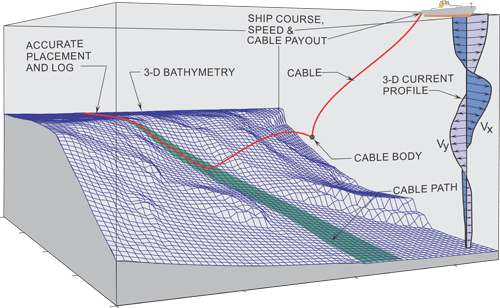
MakaiLay uses bathymetry, cable and body properties, ship navigation and payout measurements, and even real-time currents to calculate accurate 3D dynamic shapes of the cable.
This real-time cable control software allows the installer to properly deal with unplanned events that commonly occur while at-sea.
The use of MakaiLay assures the cable owner that the installer has the capacity to deal with these at-sea risks, and its use should be specified in contracts for all submarine cable lays where accuracy, reliability and risk reduction are of concern.
The heart of MakaiLay is a very thorough and rigorous mathematical model of the cable between the ship and the seabed. Makai’s model is unique in that it is the only dynamic submarine cable model that is sufficiently fast to be used in a real-time control situation.
MakaiLay is a practical at-sea working system to manage and control the installation of the submarine cable with higher accuracy and reliability than previously possible.
Need support with Makai’s subsea cable software products?
Please visit Makai’s new submarine cable software helpdesk at the link below if you have any questions on how to use our products.
MakaiLay Features
MakaiLay provides the following features for users in the cable installation process:
Planning
MakaiLay incorporates most of the features of MakaiPlan and MakaiPlan Pro.
More Info
It works in a powerful GIS framework allowing the user to easily display geographically-based data. The cable route is viewed as a geographical entity properly positioned on navigation charts, route survey data, or other GIS data. The user can create and edit the ship plan.
Simulating
MakaiLay can be used at any time to simulate a cable lay in detail and provide training to cable operator personnel.
More Info
The accurate simulation capabilities of MakaiLay enable, at a very low cost, careful planning or evaluation of any proposed cable lay operation to ensure the project specifications can be achieved at minimum cost and risk. The installer and the owner will be able to know ahead of time, with a very high degree of certainty, the accuracy and quality of the cable system installation that can be achieved with the planned equipment and deployment techniques.
Data Logging
MakaiLay logs all data critical to the cable installation and can log any other available digital data as well.
More Info
MakaiLay creates a very complete and detailed record of the operation.
Monitoring
Computes the shape of the cable between the ship and the seabed, and touchdown conditions, in real-time.
More Info
In real-time, MakaiLay accurately computes the shape of the cable between the ship and the seabed and computes a reliable record of touchdown conditions. At all times, the operator knows what the cable is doing and the impact of any ship or cable payout operation on cable touchdown conditions. MakaiLay shows detailed 3D graphics of the current and past cable shapes.
Navigating
Guides the ship along the ship plan by working directly with a DP system or by displaying guidance to the helmsman.
More Info
The navigation display provides ship guidance information and optionally shows any or all other related information in a GIS environment.
Controlling
MakaiLay is very flexible in its options for controlling cable payout and ship course and speed.
More Info
MakaiLay contains the most powerful algorithms available today for controlling seabed slack, tension and/or position.
Reporting
MakaiLay provides documentation on the cable lay in data logs and in GIS as-laid databases.
More Info
As-laid charts, tables, 3D images, and summaries can be retrieved during the lay by the main computer or remote stations throughout the vessel.
How MakaiLay Works
First, it is important to understand that the primary purpose of a cable management system is to facilitate the accurate and safe placement of the cable on the seabed. The installer is responsible for laying the cable along a given path, at a designated level of bottom slack (or tension), safely and in minimal time. While he can easily control the ship end of the cable, he is ultimately responsible for the other end of the cable that settles on the seafloor.
What happens to the cable between the ship and the seabed is the major unknown in conventional cable laying. No matter how simple or complex, all cable payout methodologies incorporate some method of describing the cable shape between the ship and the seafloor. The degree of success or failure is directly related to the ability to adequately compute the cable shape and cable touchdown conditions.
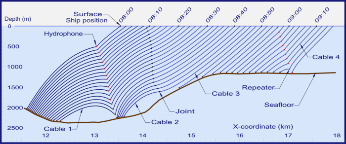
A time-stepped profile of a single cable lay over an irregular terrain. The cable is comprised of four different cable types, a joint and two heavy in-line cable bodies. This installation could not be described in steady state terms.
All cable control systems have the ability to compute cable “shapes” and use those shapes in controlling cable payout or slack. Various methods of computing cable shapes can, at first glance, look identical. Cable shapes are computed based on numerical models. Concepts such as “real-time”, “dynamic”, and “3D” can be quite casually used. However, the real test of the quality of the numerical model is how rigorous it is in computing cable shapes. A good model will predict behavior that matches well with a real cable.
For the past 45 years, several cable models have been developed based on an adaptation of steady-state cable principles developed by E.E. Zajac of Bell Labs in 1957. Zajac did a fantastic job of defining steady-state cable physics, but his approach was limited by the computing restrictions of his day.
Zajac solutions are simple to understand, simple to visualize (defined by cable angle) and have been used by cable engineers for years. Because they are based on steady-state principles, these models are fundamentally incapable of rigorously computing cable shapes that are non-steady, which occur during essentially all cable lays.
Today, thanks to modern computing power, we no longer need to make these approximations. Cable installations are nonsteady roughly between 50% and 100% of the laying time. Cables are non-steady if their shapes vary over time, and this will occur under a variety of conditions. The ship speed often varies, cable payout is not always steady, the course is not always straight, and the cable catenary often contains sensors, repeaters, and splices. An accurate model that can handle unsteady solutions is therefore needed for much of the cable lay.
Makai’s model is dynamic, 3D, fast, and rigorously adheres to the principles of cable physics. If the MakaiLay input data are correct, the computed cable shape is extremely accurate – under any conditions.
MakaiLay does not distinguish between steady state and transient conditions. The MakaiLay model treats all solutions identically and can compute the proper shape under any condition. The fundamental static and dynamic physics of the cable and ocean conditions are contained in the model, so the analysis does not change under dynamic conditions and the accuracy remains steady. There is no need for concepts such as “transient slack” or manual adjustments for other unsteady situations.
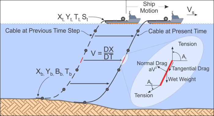
MakaiLay is a dynamic 3D model that accounts for all the relevant physical properties and forces on the cable, including wet weight, fluid drag, tension, and position. The model recalculates the cable’s shape at each time step as the ship moves forward and pays out more cable.
Makai’s cable analysis can compute solutions that are needed during practical cable laying conditions. MakaiLay can easily accommodate currents because they are simply part of the overall physics of the lay. Current data can be measured using an ADCP, and can be used for more challenging cable installations. MakaiLay’s model can also compute cable solutions where there is either bottom slack or bottom tension. MakaiLay can make a smooth transition from one solution type to another, just like a real cable.
A very important aspect of cable analysis and modeling is that a real cable is not unstable under dynamic conditions: it smoothly and gracefully follows any dynamic change in the deployment. So, a good model should do the same. If a real cable can’t jump about the seabed, the modeled cable should not jump either – if it does, there is a fundamental error in the model.
Makai’s model shows a continuous cable stepping smoothly through time with end boundary conditions matched and shapes that are physically reasonable based on prior time steps. The smooth nature of the output is a result of proper modeling of the cable lay physics.
MakaiLay User Interface
MakaiLay’s user interface is clear and easy to use, allowing the operator to clearly understand the cable’s behavior during installation.
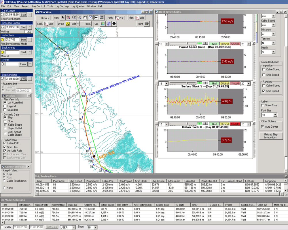
Screenshot of the MakaiLay user interface including: Workspace Controls, Plan View, Real-time Charts, Ship Instructions, and 3D Model Solutions.
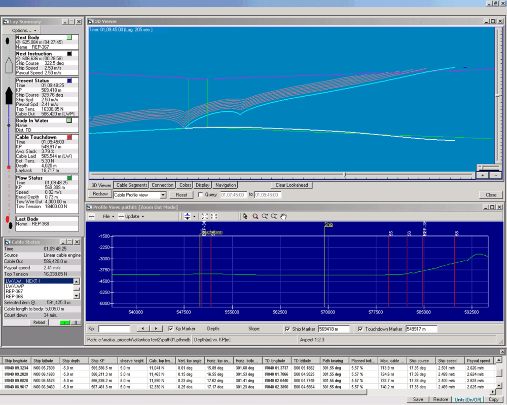
Screenshot of the MakaiLay user interface including: Lay Summary, 3D Viewer, Profile View, Cable Status, and 3D Model Solutions.
Real-Time Monitoring
MakaiLay monitors the lay and provides real-time feedback of the cable shape and touchdown conditions during the lay. MakaiLay calculates in real time a cable shape that provides where the cable is being laid, its bottom slack/tension and the location of any attached cable bodies. It interfaces with vessel instrumentation to receive the necessary real-time data to make these calculations.
MakaiLay computes the shape of the cable moving through the water column, typically every minute. This is not an approximation or a simplification of the cable shape, but rather a detailed and meticulous 3D cable computation.
Cable shapes in the water column are displayed in three dimensions and the cable slack is computed. If the computed slack goes to zero, the program switches over to computing bottom tension. If the tension goes too high, the cable on the bottom may be dragged across the seabed (changing prior touchdown locations and slack).
The software computes cable shapes under all conditions, including:
-
- Placing a cable with slack on the seafloor
- Placing a cable with tension on the seafloor
- Deploying inline cable bodies on a cable with bottom slack or tension
- Stopping and restarting a cable lay
- Recovering a cable
- Lowering or retrieving a cable free end
The monitoring system stores all computed cable shapes, dynamics, and touchdown conditions for each solution generated. These archival data are sufficiently complete so that an accurate re-creation of the entire lay can be performed in a post-lay analysis. As a minimum, these archival data include: all program input data, all cable solutions and all ship and cable payout instructions.
Using Ocean Currents
The software can log ocean currents measured in real-time using an Acoustic Current Doppler Profiler (ADCP). The current data are filtered and used by the 3D cable model to provide the user with more accurate cable shape and touchdown conditions during the installation and retrieval operations. Depending on the type of array being installed, making use of real-time current measurements can improve the cable placement accuracy by a factor of 2 to 4.

MakaiLay provides detailed records of each cable solution. This instantly informs the user of the cable’s bottom tension or slack, how far off path the cable was laid, the seabed slope at touchdown, and more.
Real-Time Control
The Control Loop
MakaiLay logs and processes data from the ship’s instruments. The 3D Cable model then computes the cable payout and navigation instructions to maintain the desired bottom conditions. MakaiLay then issues these instructions to the helmsman and the cable operator in real-time.
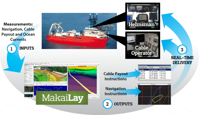
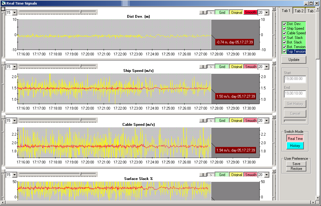
MakaiLay provides real-time charts showing the actual vessel and cable engine measurements, as well as the desired navigation and cable engine instructions.
The Control Opportunity
Incorporated within MakaiLay is the most thorough and accurate analytical cable model available today. MakaiLay can be used to reliably and practically determine the shape of the cable as it is being lowered to and installed on the seafloor and to determine touchdown conditions.
By carrying the MakaiLay at-sea analysis one step further, this same mathematical model can be used to determine future cable shapes. Therefore, touchdown conditions in the immediate future can be reasonably predicted by the model. Having such a prediction is like having a crystal ball – corrections can be made to the installation procedures now to avoid undesirable touchdown conditions in the future.
The three most important touchdown properties for cable installation are slack, tension, and position. For most telecommunication cables, slack is the most important goal, tension is undesirable (if slack is satisfied, there will be no tension), and position is of secondary importance. For telecommunication cables, MakaiLay is used to predict and direct cable payout such that bottom slack is controlled at the RPL specified levels.
Power cables are installed with low levels of bottom tension. MakaiLay solutions are equally valid for a cable being laid with bottom tension. Some cables require very accurate placement on the seabed. In these cases, MakaiLay can be used as a real-time control system to direct the ship along an optimal course in order to keep the bottom cable near the desired bottom path.
In other cases, cable operations require a trade-off between placement accuracy and cable operation time. MakaiLay can optimize this trade-off so that the amount of time to install and recover cable is minimized while the operation stays within its design specifications.
The section entitled “Program Validation” illustrates several actual cable installations where the control capabilities of MakaiLay were demonstrated.
Why Control?
No installation ever follows the plan exactly and many deviate dramatically from the original plan.
More Info
If a cable installation accurately follows a detailed and proper ship plan, why is there a need for real-time control?
The reality is that no installation ever follows the plan exactly and many deviate dramatically from the original plan. The ship speed is never exactly according to the plan, and cable payout likewise does not follow the plan perfectly. Often, there are unplanned stops and contingency situations that could not have been anticipated. Equipment failures and weather often dictate major variations from the original plan. Once the ship conditions are not as anticipated, how should the cable be handled?
With real-time control and the full power of the MakaiLay model at sea, the correct adjustments to the plan can be easily and reliably made before they become serious problems. Cable operations can be monitored and reasonably controlled under nearly any real- time condition.
Seafloor Slack/Tension Control
MakaiLay has the ability to control cable payout speed in order to actively control the cable slack/tension on the seafloor.
More Info
MakaiLay uses the 3D dynamic cable model algorithms to predict the near-future cable shapes and touchdown conditions. It computes the appropriate cable payout speed in order to achieve the desired cable touchdown conditions.
The system displays forecasts of the future cable shape profiles and graphs of future touchdown conditions, surface conditions, ship speed, and payout speed.
Seafloor Position Control
For more advanced cable installations, MakaiLay can be used for position control of the cable.
More Info
In this case, future forecasts, often looking an hour or more into the future, are used to optimize a set of ship instructions to keep a cable optimally aligned along a bottom path. Simultaneously with position control, MakaiLay provides seabed slack control. For years, the cable industry harbored the concept that once a cable left the stern of the ship, there was nothing that could be done to control its placement on the seabed.
This concept was a direct result of the steady-state cable models that were prevalent at the time. With MakaiLay in simulation mode, the capacity for position control can be quantified for any given installation. Makai has demonstrated real-time position control on several cable installations (see “Program Validation”). The ability to make informed decisions at sea in response to any situation has dramatic impact on the reliability and accuracy with which cables can be installed.
Simultation
MakaiLay allows the user to dynamically simulate the complete cable installation (or any portion of it) either before or after the cable installation. The simulator is very valuable for:
-
- Understanding how a cable will behave under certain conditions.
- Determining whether a cable can be installed using specific equipment or with a specific installation plan.
- Training cable operators by showing them exactly what the cable will do under specific ship and cable payout instructions.
- Creating detailed ship plans in advance of a cable lay.
- Performing detailed post-lay analysis.
In simulation mode, MakaiLay behaves exactly as it does at sea. Detailed 3D cable solutions are available to the operator. The user can determine whether a cable installation is feasible, given certain RPL requirements, ship limitations, and environmental conditions. You can make all your mistakes in advance on the simulator when they can be easily corrected and before they become costly at-sea disasters. The cable installation can be simulated in detail and refinements can be made to the preliminary Ship Plan. You can look at the entire installation and compute the seafloor slack, tension, and location along all or portions of the route. By quickly scanning the graphical GIS output record produced by MakaiLay, the success or failure of the cable placement will be immediately apparent.
Hardware
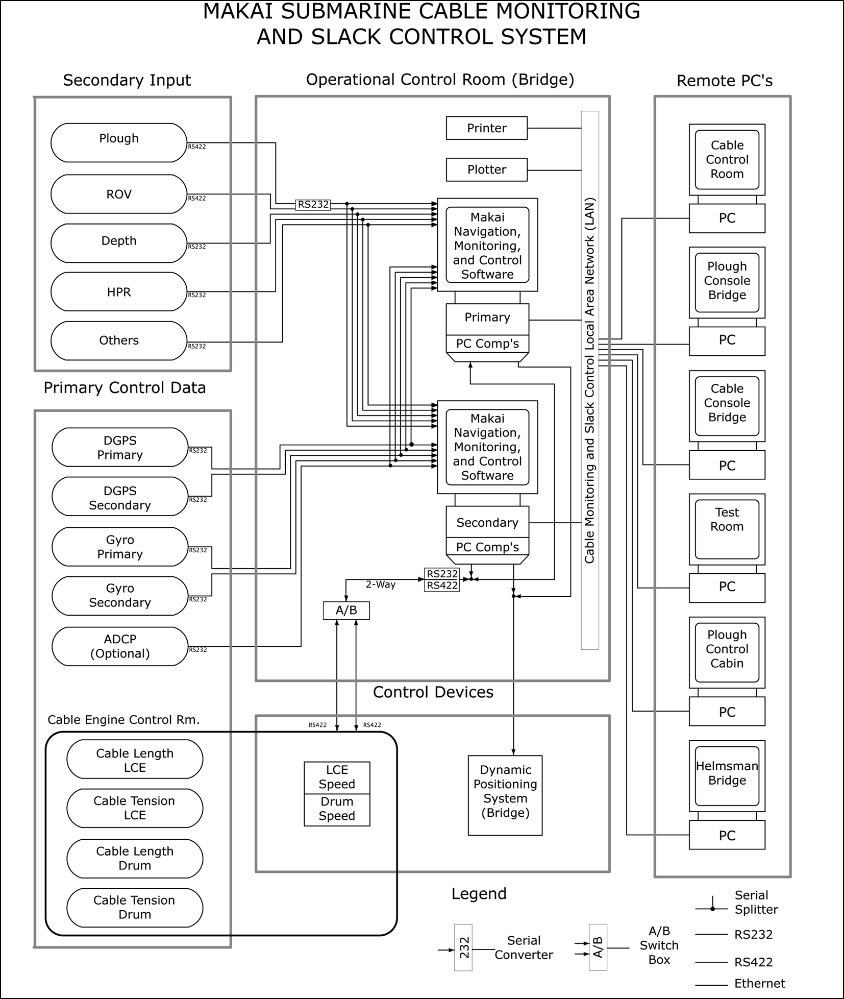
Two main computers (primary and backup) are located on the bridge. The following is a typical list of computer hardware for a cable ship:
-
- Intel 64-bit processor
- Windows 7/8/10 Professional operating system (English version)
- 8 GB RAM
- Dual monitor capable graphic card
- Two, 500GB hard drives
- Two, 21″ monitors
- Mouse, keyboard, & USB port
- Ethernet card (wired)
The 2 main computers are to be fitted with identical data acquisition boards in order to be connected through serial lines to IAS for Dynamic Positioning, cable handling machinery control system, 2 DGPS, gyros, echo sounder, HPR, and plough control system.
All the main processing of MakaiLay is performed on a single PC computer using a Windows operating system. A fully redundant backup computer operates in parallel. Data logging is done in parallel and cable solutions are computed on both machines simultaneously. The system can switch to the backup at any time. MakaiLay is quite flexible in terms of its configuration beyond the main and backup computers.
Input data can be provided via RS232/422/485 or Ethernet connections. MakaiLay’s standard configuration has 32 RS232/422 input ports and more can be added if needed. Output from MakaiLay goes to the DP equipment and to the cable room – both locations receive instructions from MakaiLay. Those instructions can be sent by a direct wire (in case of automatic control) or via a Makai-driven display at each location (manual control). Client computers are distributed throughout the ship and any number can be used. Client computers are stand-alone PC’s with the MakaiLay client software. The clients are connected to the main computers via a dedicated Ethernet.
Program Validation
How Do We Know It Works?
Makai’s Cable Division was formed in 1983, and since that time our engineers have performed rigorous physical and cross-model validations of our 3D cable model. These projects have consistently proven that the model is accurate and reliable.
The following three cable installations describe the conditions under which MakaiLay was initially developed and validated:
-
- Power cables;
- Lightweight cables while measuring currents, and;
- Lightweight cables without current measurements.
Precision Calibration
The Hawaii Deep Water Cable Program (HDWCP) was a R&D program co-sponsored by the U.S. Department of Energy and the State of Hawaii. The purpose of this program was to determine the technical feasibility of deploying a submarine power transmission cable between the Island of Hawaii and the Island of Oahu.
This project posed unique challenges never encountered by any previously laid power cable. The cable had to be laid with very small bottom tensions and to an accuracy of ±12 meters in waters 1,920 m deep. Survey results quickly determined that conventional cable laying techniques were not suitable due to the roughness and difficulty of the cable route and the accuracy required.
Makai developed a detailed analytical/numerical model that was sufficiently fast and sufficiently accurate to simulate, analyze, and lay this power cable. This model eventually formed the heart of a real-time control system now known as MakaiLay.
During installation, Makai’s system guided the cable ship and directed the cable payout in real-time. Current profiles were measured with an ADCP and incorporated into the real-time solutions.
The final result was that the RMS error for all portions of the 20 km of cable laid was 4.7 meters, considerably less than the 12m goal. Bottom cable tension tolerances were equally well met.
This program demonstrated that cable lays could be carefully controlled with the use of the proper analytical tools incorporated into the control system. This program also validated the mathematical code used in those controls.
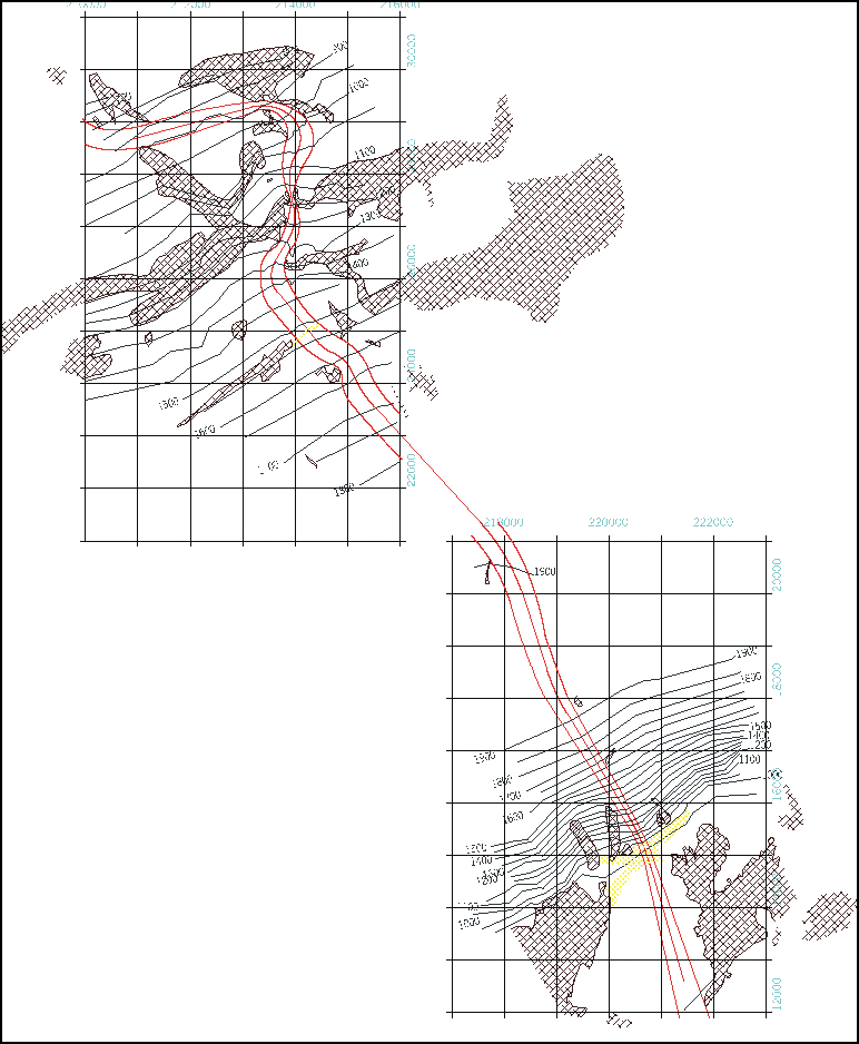
MakaiLay was used to install test cables in depths up to 1920m across the treacherous Alenuihaha channel in the Hawaiian Islands. The test cables were placed on the seabed with unprecedented accuracy, and independent surveys were performed to validate the cable model.
SOAR II
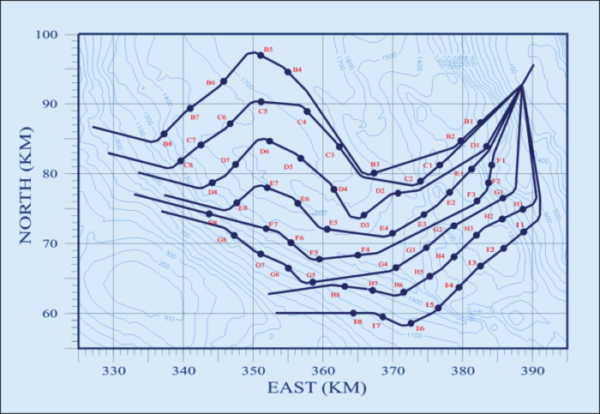
In 1990, after the successful completion of the HDWCP, Makai Ocean Engineering was contracted by the U.S. Navy, Naval Facilities Engineering Command (Chesapeake Division), for the installation of the Phase II of the Southern California Anti-Submarine Warfare Range (SOAR II).
More Info
The SOAR II project involved the deployment of eight, 40 mile long cables, each having 8 hydrophones and several repeaters.
The cable lay took place in maximum water depths of 1,800 m off San Clemente Island in California. The goal was to lay the hydrophones on targets (specific X and Y locations on the bottom) along cable paths with multiple abrupt turns. The maximum allowable error at the bottom was 90 meters. In this case, the cable not only had to follow a pre-determined path, but the bottom cable slack had to be carefully controlled in order to hit the targets.
Makai made several modifications to our software to accommodate lightweight cables, slack conditions, bodies (repeaters, transponders, hydrophones, etc.) attached to the cable, and a high degree of control on bottom cable slack.
During the cable lay Makai provided instructions to the ship and the cable engines every five minutes and stayed fully in control of the lay even during unplanned stops and severe changes in currents.
The project was very successful and a fully functional surveillance range is now in place. According to an independent survey completed by the U.S. Navy, the mean value of the hydrophone location from the target center was 46 m, half the maximum allowable error.
One of the most valuable services provided by Makai to the Navy was the pre-lay simulation and analysis (with the forerunner of MakaiPlan Pro). Makai was able to provide a shopping list to the Navy showing the equipment (and cost) required vs. performance expected, based on detailed modeling of the actual installation. The final results were slightly better than Makai’s predictions. In summary, a cable slightly lighter than today’s lightweight telecommunication cable was deployed while measuring currents, and the average placement accuracy was 3.5 percent of water depth.
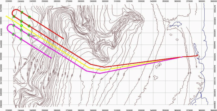
AURA – Acoustic Underwater Range in Australia
Makai’s software determined: (a) the placement accuracy expected for a set of cable laying equipment and oceanographic conditions, and (b) the degree of cable slack control that could be achieved to minimize the cable length used and avoid the use of additional expensive repeaters.
More Info
This project involved the use of a “ship of opportunity“ to lay three cables, each 210 km long, in waters ranging from 10 m to 4,200 m deep. These cables contained several in-line hydrophones that had to be placed on specific targets along a pre-established route.
In 1992, Makai’s simulator was used to determine: (a) the placement accuracy expected for a specific set of cable laying equipment and oceanographic conditions, and (b) the degree of cable slack control that could be achieved to minimize the total length of cable used and to avoid the use of additional expensive repeaters. In 1994, Makai’s software was used to accurately place the hydrophones off SW Australia.
A post-deployment survey completed by the Navy determined that the final average placement error for the hydrophones was within 2% of the values predicted by previous simulations run with the Makai Simulator under similar deployment conditions. Despite using a “ship of opportunity“ with poor sea keeping capabilities in high sea states, the use of Makai’s at-sea control software allowed the cable layer to accurately control the placement of one of the cable systems in sea states 6-7 (sustained winds of 30 knots, 10 ft swells and 8 ft seas).
The absolute level of placement accuracy was 11% of water depth. Currents were not measured and were not incorporated into the control system. Cable weights were lighter than conventional lightweight cables used today and the hydrophones were equivalent in weight to modern cable splices. Installation speeds varied from 2 to 5 knots. During this installation, the control system also demonstrated that it could accurately control the cable deployment at ship speeds of 5 knots in depths of water of only 60 m.
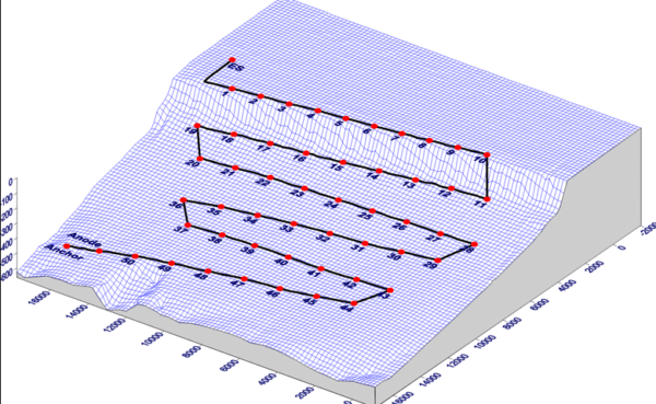
PTS Bahamas
Makai served as a subcontractor to the U.S. Naval Warfare Center for the installation of the Portable Tracking System (PTS). Initially, Makai was contracted to simulate the deployment operation using Makai´s cable lay simulator to determine the slack control and level of placement accuracy that could be expected during the deployment of the fiber optic cable and 51 in-line hydrophones that made up the cable system. The PTS was successfully deployed several months later using Makai’s control software and the final touchdown coordinates were independently validated by a post-deployment survey.
Cross-Model Validation
Makai has performed cable modeling for the US Navy of the installation of micro cables 2 to 4 mm in diameter with multiple hydrophones. This is an extremely complex, numerically sensitive, and computationally challenging simulation. The Navy compared our results with Navy at-sea test results and the best software programs available in the US Navy. Makai’s solutions had better accuracy and were computed at many hundreds of times faster than any competing software.
Services
Makai provides a comprehensive set of cable-related services that leverage the expertise of our engineers and the sophisticated tools in our software products. Makai’s services include assistance with planning your cable route, simulating your lay, and installing your telecom or power cable at-sea. We also provide submarine cable software training.
Planning
Makai offers submarine cable planning services to assist cable owners and planners in the preliminary stages of cable route planning.
Simulation
Makai uses the advanced simulation features in MakaiPlan Pro to run simulations to answer specific questions about installations of cables and arrays.
Installation
Makai proves software, hardware, and personnel for the control of at-sea operations, and performs post-lay analysis to develop as-laid conditions.
Training
Makai provides both on-site or remote training courses to learn how to use the Makai software suite. Different levels of training fit all levels of operators.
Products
Makai's software products support the entire lifecycle of submarine cables, including planning, installation, repair, and recovery.
MakaiPlan
Submarine Cable Route Planning Software
MakaiPlan Pro
Submarine Cable Planning and Simulation Software
MakaiLay
At-Sea Cable Lay Monitoring & Control System
Modules
Makai provides additional modules to supplement the products above for our clients' specific applications.
Interested in Makai’s Submarine Cable Software and Services?
ReACH OUT!
Contact us by sending in this form any time you need professional support or have any questions. You can also fill in the form to leave your comments or feedback for Makai’s team.
Need support with Makai’s subsea cable software products?
Please visit Makai’s new submarine cable software helpdesk at the link below if you have any questions on how to use our products.

